- 您现在的位置:买卖IC网 > Sheet目录1203 > COREPCIF-RM (Microsemi SoC)IP MODULE COREPCIF
�� �
�
�Single-Cycle� Read� and� Write�
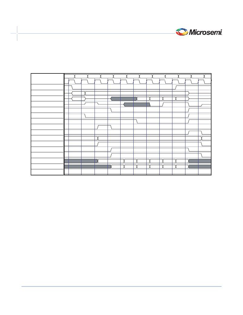
�Figure� 6-1� to� Figure� 6-3� on� page� 54� show� basic� single-cycle� read� and� write� accesses� to� the� backend.� The� core� will� pulse�
�DP_START� active� and� indicate� whether� it� is� a� read� or� write� cycle� and� which� BAR� is� being� accessed.� BAR_SELECT�
�and� RD_CYC/WR_CYC� will� become� valid� on� the� same� clock� cycle� where� DP_START� is� asserted� and� will� remain�
�active� until� DP_DONE� is� asserted.� They� are� deasserted� on� the� clock� cycle� after� DP_DONE.� Although� the� PCI�
�interface� requests� only� a� single� data� word� read,� the� core� may� read� more� than� one� word� from� the� backend� interface.�
�For� read� cycles,� the� core� indicates� that� it� is� ready� to� read� data� by� asserting� RD_STB_OUT.� The� backend� logic� indicates�
�that� it� has� data� available� by� asserting� RD_STB_IN.� When� both� of� these� signals� are� active,� the� core� will� read� data� from�
�the� backend.� If� RD_SYNC� =� 0,� data� is� sampled� on� the� clock� edge� during� which� the� strobes� are� active� (� Figure� 6-1� ).�
�When� RD_SYNC� =� 1,� data� is� sampled� on� the� following� clock� edge� (� Figure� 6-2� on� page� 53� ).�
�The� PCI� specification� states� that� the� maximum� delay� from� FRAMEN� assertion� to� the� first� data� word� transferred� on� the�
�PCI� bus� is� 16� clock� cycles.� The� core� takes� two� clock� cycles� from� the� time� FRAMEN� is� asserted� to� assert� DP_START.�
�RD_STB_OUT� is� asserted� one� clock� cycle� later,� and� then� an� additional� two� clock� cycles� are� required� for� the� data� to� pass�
�back� through� the� core.�
�The� backend� must� assert� RD_STB_IN� within� 11� clock� cycles.� If� the� backend� does� not� assert� RD_STB_IN� within� this�
�time,� the� core� will� automatically� terminate� the� PCI� transfer� with� a� Target� retry.� When� RD_SYNC� =� 1,� an� additional�
�cycle� of� delay� is� added� at� the� backend� interface,� reducing� the� initial� backend� latency� to� 10� clock� cycles.�
�Once� a� data� burst� has� started,� data� must� be� transferred� every� eight� clock� cycles.� If� the� backend� fails� to� provide� data� at� this�
�rate,� the� core� will� terminate� the� PCI� cycle� with� a� disconnect� without� data� to� maintain� PCI� compliance.�
�When� the� SX-A� or� RTSX-S� families� are� used,� the� core� inserts� an� additional� clock� cycle� of� latency� internally.� Thus,� in�
�this� case,� the� backend� maximum� initial� latency� is� reduced� by� one� clock� cycle.� This� is� summarized� in� Table� 6-2� on�
��cycle�
�0�
�1�
�2�
�3�
�4�
�5�
�6�
�clk�
�framen�
�cben[3:0]�
�ad[31:0]�
�par�
�devseln�
�irdyn�
�trdyn�
�dp_start�
�dp_done�
�bar_select[2:0]�
�rd_cyc�
�rd_stb_out�
�rd_stb_in�
�6�
�ADDR�
�0�
�0�
�0�
�mem_add[15:0]�
�mem_data_in[31:0]�
�0000�
�0�
�0004�
�1�
�0008�
�2�
�rd_sync�
�Figure� 6-1� ·� Backend� Read� Cycle� (RD_SYNC� =� 0)�
�52�
�v4.0�
�发布紧急采购,3分钟左右您将得到回复。
相关PDF资料
COREU1LL-AR
IP MODULE COREU1LL
COREU1PHY-AR
IP MODULE COREU1PHY
CORR-8BIT-XM-UT2
SITE LICENSE IP CORRELATOR XP
CP2-GSA-L
CONN SHIELD LOWER TYPE A 22
CP2-HSA110-1
CONN SHROUD CPCI 2MM TYPE A 22
CP2-HSC055-4
CONN SHROUD CPCI 2MM TYPE C 11
CP2-K3567-SR-F
COMPACT PCI - MISC
CP2105EK
KIT EVAL FOR CP2105
相关代理商/技术参数
COREPCIF-RMFL
功能描述:IP MODULE 制造商:microsemi corporation 系列:- 零件状态:在售 类型:许可证 应用:- 版本:- 许可长度:- 许可 - 用户明细:- 操作系统:- 配套使用产品/相关产品:Microsemi 器件 媒体分发类型:- 标准包装:1
COREPCIF-UR
功能描述:HW/SW/OTHER 制造商:microsemi corporation 系列:* 零件状态:在售 标准包装:1
COREPCI-SN
制造商:ACTEL 制造商全称:Actel Corporation 功能描述:CorePCI v5.41
COREPCI-SR
制造商:ACTEL 制造商全称:Actel Corporation 功能描述:CorePCI v5.41
COREPCI-UR
制造商:ACTEL 制造商全称:Actel Corporation 功能描述:CorePCI v5.41
COREPCI-XX
制造商:ACTEL 制造商全称:Actel Corporation 功能描述:CorePCI v5.41
COREPRO LEDBULB 10.5-60W B
制造商:Philips Lumileds 功能描述:
COREPRO LEDBULB 10.5-60W E
制造商:Philips Lumileds 功能描述: